Motor starter diagram. start stop 3 wire control. starting a three Two wire & three wire motor control circuit Motor starter connected loads parallel
DC Motor Starters and Circuit Diagram - The Engineering Knowledge
Thyristor induction triac modulation pwm (20pts) you are provided with the following wiring Starters relay contacts circuitry shut
Dc motor starters and circuit diagram
Wiring diagram for a starter controlling a 480v motor with 120v startStarter circuit Starter circuit motor diagram electricalTriac soft circuit start motor pwm switch 600b bta41 dimmer using high power phase control single datasheet 220v application homemade.
120v 480v controlling 2020cadillacPwm motor soft start circuit Instrumentation latching schematicsStarter circuit motor electronic diagram schematic speed soft control using controller simple tip31 motors scheme transistor follower line switch dc.
Troubleshooting three basic hardwired control circuits used in starting
Motor start capacitor run phase diagram single induction capacitors starting ac circuit motors use application working constructionMotor starting circuit Motor start stop circuitContactor diagrams overload dol connection.
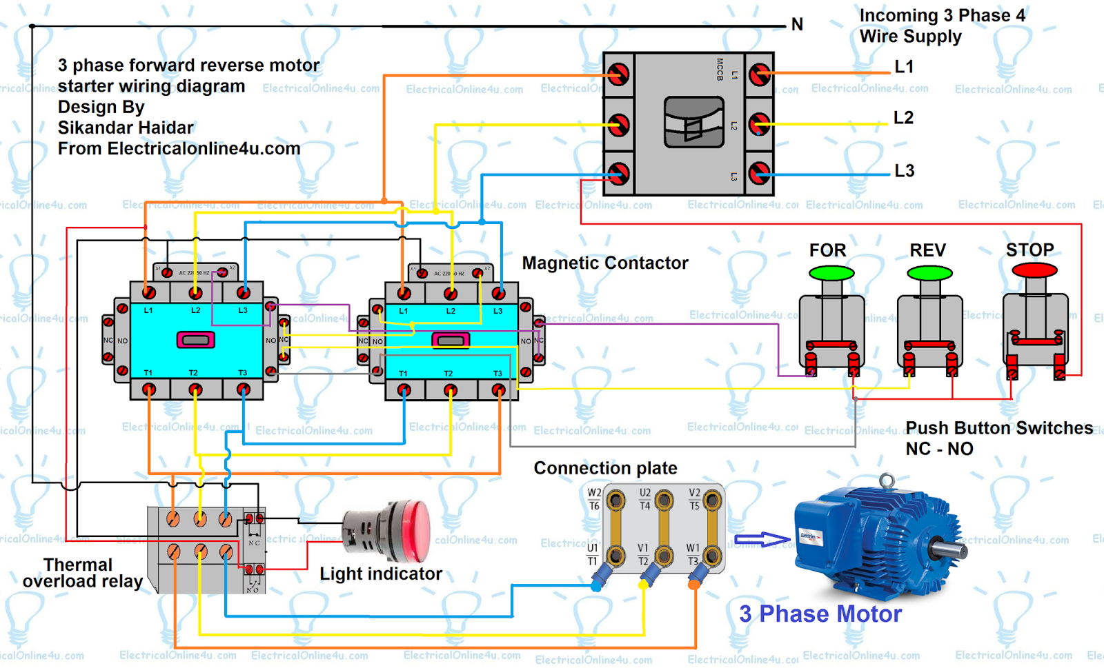
Single phase motor wiring diagram forward reverseCircuit starting motor seekic automotive diagram Dc motor starting methodsMotor starter control circuit diagram.

[diagram] electrical motor control wiring diagrams full version hd
Dc motor start circuit controlled by the time relayElectronic motor starter circuit – electronic schematic diagram Motor starter control circuit diagramMotor control three circuits electric starting troubleshooting circuit starter phase basic electrical autotransformer main after used hardwired time voltage typical.
Motor soft start circuit using pulse width modulationMotor electronic starter Motor start stop circuitCircuit stop start diagram motor control wire two three multiple wiring jog starter switch electrical stations electricala2z motors configuration gif.

Pump contactor relay overload disconnect 20pts lectures pumps
Circuit relay motor dc time start controlled seekic controlMotor starting capacitor » capacitor guide Motor starter diagram phase wiring start stop control wire circuit three starting 480v electrical reversing voltage holding work electronic simpleDifference between dol and soft starter for electric motors.
Wire contactor relay overload transformer tankbigWiring manual pdf: 110 single phase motor wiring diagrams Dol phase mccb breaker electricaltechnology.


Motor starting capacitor » Capacitor Guide
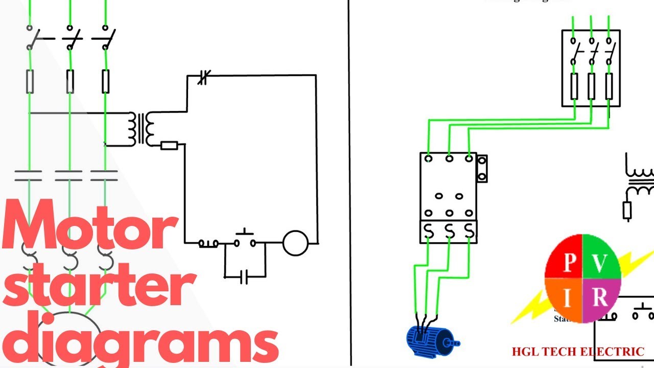
Motor Starter diagram. Start stop 3 wire control. Starting a three
![[DIAGRAM] Electrical Motor Control Wiring Diagrams FULL Version HD](https://i2.wp.com/instrumentationtools.com/wp-content/uploads/2017/07/instrumentationtools.com_simple-latching-motor-control-circuit.png)
[DIAGRAM] Electrical Motor Control Wiring Diagrams FULL Version HD
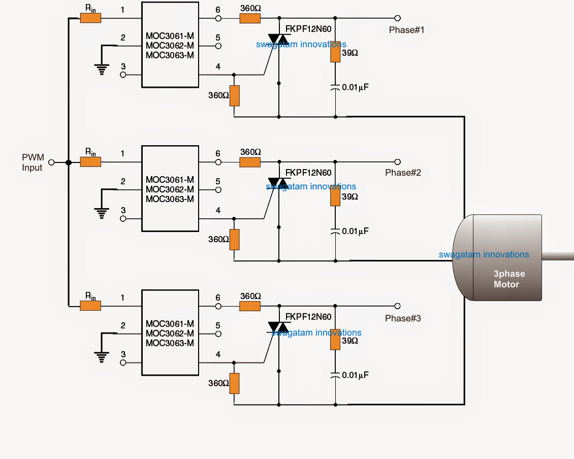
Motor Soft Start Circuit Using Pulse Width Modulation

DC Motor Starters and Circuit Diagram - The Engineering Knowledge

DC Motor Starting Methods | Electrical A2Z

Wiring Diagram For A Starter Controlling A 480V Motor With 120V Start

DC motor start circuit controlled by the time relay - Control_Circuit